Evo X Oil Catch Can Guide: PCV Routing, Installation & Maintenance
Route an Evo X oil catch can so the system can actually work
A catch can is not just a black cylinder in the engine bay. Valve-cover fitment, hose routing, drain access and regular inspection determine whether the installation stays clean and dependable.
An Evo X oil catch can separates oil mist and moisture from crankcase vapors before those vapors are vented or returned according to the kit design. On the 4B11T engine, the goal is not to “fix” worn rings, excessive blow-by or a blocked PCV system. It is to manage normal vapor contamination while keeping the hoses, fittings and drain serviceable.
Confirm the valve-cover version first
The featured STM kit is listed for 2008–2015 Mitsubishi Lancer Evolution X applications with the plastic valve cover. That limitation matters because the fittings, hose connections and mounting instructions are built around a specific cover layout. If the car has an aluminum aftermarket cover, a different PCV arrangement or previous breather modifications, stop and verify compatibility before purchasing.
- Confirm the car is a 2008–2015 Evo X with the plastic valve cover.
- Inspect the existing PCV valve, cover ports and hoses for cracks, sludge or stripped threads.
- Check that the lower radiator support and frame-rail mounting area are straight and corrosion-free.
- Identify safe hose paths away from the radiator fan, belts, pulleys, exhaust heat and sharp edges.
- Plan access to the brass drain fitting from under the car before tightening the mount.
Featured STM plastic-valve-cover catch-can kit
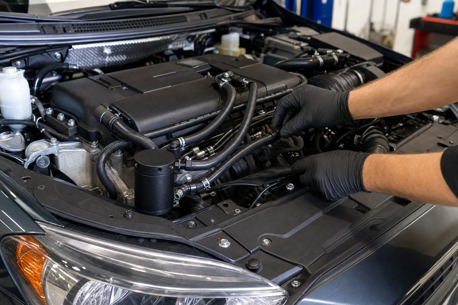
The STM engine oil catch can for the Evo X plastic valve cover uses a TIG-welded aluminum body with wrinkle-black powder coat, -10AN fittings and black nylon hose. The listing says the can mounts low on the radiator support or bottom frame rail for under-car drain access.
The listed package includes the catch can, STM valve-cover fitting, two 5/8-inch breather filters, two five-foot -10AN nylon hoses, two 45-degree fittings, one 90-degree fitting, hose clamp, mounting hardware, adhesive buffer and brass drain fitting.
Understand the specified hose routing
According to the product installation notes, one 45-degree fitting attaches to the passenger side of the mounted catch can. That hose runs to the other 45-degree fitting on the STM valve-cover fitting that replaces the PCV valve. The 90-degree fitting mounts on the driver side of the can, with its hose leading to the driver-side valve-cover connection and secured with the supplied clamp.
Lay out the full route before cutting hose. Leave enough length for engine movement and service access, but avoid low loops that can collect liquid or loose arcs that reach the fan. Nylon hose is less likely to scratch painted surfaces than stainless braided line, yet it still needs support and heat clearance.
Installation sequence
| Stage | Action | Verification |
|---|---|---|
| 1. Prepare | Work on a cool engine, disconnect components only as required and clean around every open port. | No dirt can enter the valve cover. |
| 2. Mount | Position the can on the specified lower support using the supplied hardware and buffer. | Body is stable, drain reachable and no contact with the frame. |
| 3. Fit ports | Install the STM valve-cover fitting and can fittings according to the maker’s notes. | Correct orientation with no cracked plastic or cross-threading. |
| 4. Route | Measure and cut the two nylon hoses, preserving smooth bends. | No kinks, fan contact, belt contact or exhaust exposure. |
| 5. Secure | Tighten fittings and clamp to the supplied guidance, then support the hose runs. | Nothing rubs paint or moves into a hazard. |
| 6. Test | Start the engine, inspect idle behavior and check every joint for leaks. | No hiss, oil seepage, warning light or collapsed hose. |
Why sealant work needs restraint
The product notes suggest a small amount of glue or epoxy when installing the large STM fitting in the valve cover. Use only the material and quantity approved by the kit maker. Excess adhesive can squeeze into the ventilation passage, contaminate the engine or make later service difficult. The plastic cover can also crack if a fitting is forced or over-tightened.
Maintenance schedule
There is no universal drain interval because collection depends on engine condition, boost, ambient temperature and trip length. Inspect the can soon after installation, then shorten or extend the interval based on what it actually collects. Cold weather and repeated short trips can produce a watery emulsion; hard use can increase oil mist.
- Check the catch-can level after the first few drives.
- Drain before the collected fluid can reach the hose ports.
- Inspect filters for saturation or restriction.
- Look for softened, kinked or chafed hose.
- Recheck the low mount, buffer and drain fitting after road debris or underbody service.
- Investigate a sudden increase in collected oil instead of assuming it is normal.
Troubleshooting after installation
Rough idle or a new whistle
Check for a loose fitting, open vacuum path or incorrect PCV routing. A catch can should not introduce an uncontrolled air leak.
Oil appears around the valve cover
Verify that crankcase pressure is not building from a kinked hose, blocked filter or wrong connection. The catch can does not replace diagnosis of a damaged gasket or cover. If the leak is lower on the engine, use our Evo X oil-pan leak guide to separate pan seepage from oil traveling down the block.
The can stays completely dry
A dry can may be normal for a short interval, but it can also indicate reversed routing, an unsealed fitting or vapor bypass. Compare the installation with the supplied route.
The hose collapses
Stop driving until the restriction and hose specification are corrected. A collapsed line can prevent proper crankcase ventilation.
Frequently asked questions
Does this kit fit an aluminum valve cover?
The featured product is specifically listed for the plastic Evo X valve cover. Verify another solution for a different cover.
Does a catch can add horsepower?
It should not be treated as a guaranteed power upgrade. Its purpose is vapor and contamination management.
Can I ignore the drain because the can is mounted low?
No. Low mounting improves packaging and drain access, but collected fluid still requires routine inspection and disposal.
Fit the right cover, preserve ventilation and keep the drain accessible
Plan both hose paths before cutting, protect the low mount and use the first few inspections to establish a maintenance interval for the actual car.